Pinhole Camera Model
The simplest camera model is pinhole model which decribes the mathematical relationship of the projection of points in 3d-space onto a image plane. Let the centre of projection be the origin of a Euclidean coordinate system, and the plane , which is called the image plane or focal plane. Under pinhole camera model, a point in space with coordinates is mapped to the point on the image plane using triangles as shown in Figure 1. Ignoring the final image coordinate, the central projection mapping from 3d world space to 2d image coordinates is,
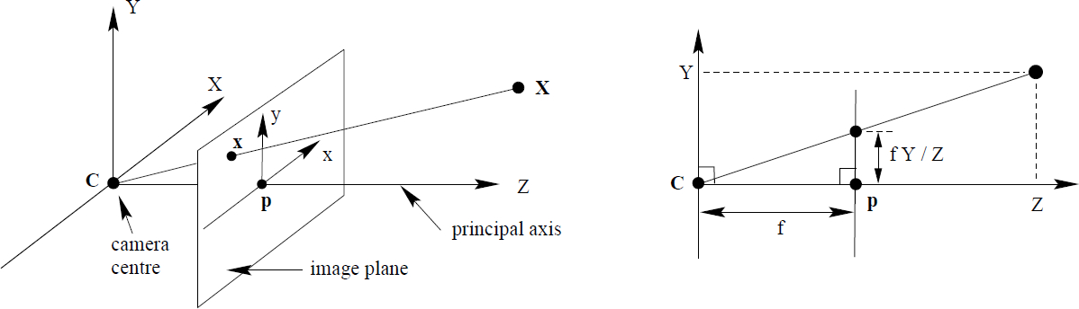 Figure 1. Pinhole camera geometry. The centre of projection is called the camera centre or the optical centre. The line from the camera centre perpendicular to the image plane is called the principal axis or principal ray. The point where the principal axis
meets the image plane is called the principal point. The plane through the camera
centre parallel to the image plane is called the principal plane of the camera. C is the camera centre and p the principal point. The camera centre is here placed at the coordinate origin [Hartley and Zisserman, 2003].
Figure 1. Pinhole camera geometry. The centre of projection is called the camera centre or the optical centre. The line from the camera centre perpendicular to the image plane is called the principal axis or principal ray. The point where the principal axis
meets the image plane is called the principal point. The plane through the camera
centre parallel to the image plane is called the principal plane of the camera. C is the camera centre and p the principal point. The camera centre is here placed at the coordinate origin [Hartley and Zisserman, 2003].
Assuming the world and image points are represented in homogeneous coordinates, then central projection can simply expressed as a linear mapping between their homogeneous coordinates in terms of matrix multiplication by,
Principal point offset: In theory the origin of coordinates in the image plane assumed to be at the principal point. This may not be true in practice, hence, the Eq. \eqref{eq:k1} is express as,
First matrix in the right side of Eq. \eqref{eq:k2} called camera calibration matrix, usually expressed by . For added generality, the calibration matrix can be express as,
where is referred to as the skew parameter which is zero for most of the cameras. and where and represent the focal length of the camera in terms of pixel dimensions in the x-axis and the y-axis respectively, and is coordinate of the principal point.
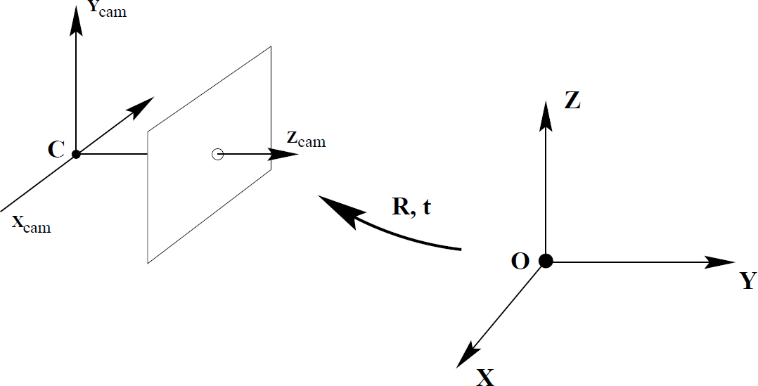 Figure 2: The Euclidean transformation between the world and camera coordinate frames [Hartley and Zisserman, 2003].
Camera rotation and translation: The Subscripts cam in above equations is to emphasize that the points are represented as camera coordinate frame. In general, points in space is determined by the world coordinate frame. The camera coordinate and world coordinate frames are related by rotation and translation. As it is shown in Figure 2, if is the coordinate of the point in the world coordinates, then is transformed by,
where R is rotation matrix and t is translation matrix.
Putting eveything together the formula for general mapping of pinhole camera in world coordinate frame x is defined by,
So that, the general pinhole camera matrix, P, can be represented by,
and it has 9 degrees of freedom,
- Three for K, namely, , , and
- Three for rotation matrix R
- Three for translation t
Internal camera parameters, K , show the internal orientation of the camera and it is fixed.
External parameters, R and t show camera orientation and position to a world coordinate system.
References
Richard Hartley and Andrew Zisserman. Multiple view geometry in computer vision. Cambridge university press, 2003.